DELIVERY PROGRAM
Product range
Accessories
Accessories
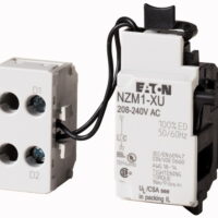
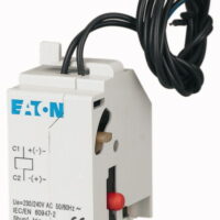
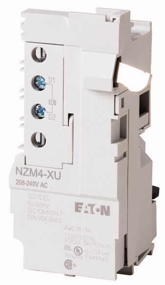
Undervoltage release
Accessories
Undervoltage releases
Standard/Approval
UL/CSA, IEC
Construction size
NZM4
Description
Non-delayed disconnection of NZM circuit-breaker or N switch-disconnector when the control voltage sinks below 35 – 70% US.
For use with emergency-stop devices in connection with an emergency-stop button.
When the under-voltage trip is switched off, accidental contact with the circuit breaker’s primary contacts is prevented when switched on.
Undervoltage releases cannot be installed simultaneously with NZM…-XHIV… early-make auxiliary contact or NZM…-XA… shunt release.
Connection type
With bolt connection
Auxiliary contacts
without auxiliary contact
Rated control voltage [Us]
208 – 240 V 50/60 Hz V
For use with
NZM4(-4), N(S)4(-4)
TECHNICAL DATA
Undervoltage release
Rated control voltage [Us ]AC [Us ]
208-240 V AC
Rated control voltage [Us ]Rated control voltage [Us]
208 – 240 V 50/60 Hz V
Operating rangeDrop-out voltage
0.35 – 0.7 x Us
Operating rangePick-up voltage [x Uc]
0.85 – 1.1
Power consumptionACPick-up AC
3.6 VA
Power consumptionACSealing AC
3.6 VA
Power consumptionDCPick-up DC
2.5 W
Power consumptionDCSealing DC
2.5 W
Maximum opening delay (response time until opening of the main contacts)
23 ms
Minimum command time
10 … 15 ms
Terminal capacities
Solid or flexible conductor, with ferrule
1 x (0,75 – 2,5)
2 x (0,75 – 2,5) mm2
2 x (0,75 – 2,5) mm2
1 x (18 … 14)
2 x (18 … 14) AWG
2 x (18 … 14) AWG
DESIGN VERIFICATION AS PER IEC/EN 61439
IEC/EN 61439 design verification
10.2 Strength of materials and parts10.2.2 Corrosion resistance
Meets the product standard’s requirements.
10.2 Strength of materials and parts10.2.3.1 Verification of thermal stability of enclosures
Meets the product standard’s requirements.
10.2 Strength of materials and parts10.2.3.2 Verification of resistance of insulating materials to normal heat
Meets the product standard’s requirements.
10.2 Strength of materials and parts10.2.3.3 Verification of resistance of insulating materials to abnormal heat and fire due to internal electric effects
Meets the product standard’s requirements.
10.2 Strength of materials and parts10.2.4 Resistance to ultra-violet (UV) radiation
Meets the product standard’s requirements.
10.2 Strength of materials and parts10.2.5 Lifting
Does not apply, since the entire switchgear needs to be evaluated.
10.2 Strength of materials and parts10.2.6 Mechanical impact
Does not apply, since the entire switchgear needs to be evaluated.
10.2 Strength of materials and parts10.2.7 Inscriptions
Meets the product standard’s requirements.
10.3 Degree of protection of ASSEMBLIES
Does not apply, since the entire switchgear needs to be evaluated.
10.4 Clearances and creepage distances
Meets the product standard’s requirements.
10.5 Protection against electric shock
Does not apply, since the entire switchgear needs to be evaluated.
10.6 Incorporation of switching devices and components
Does not apply, since the entire switchgear needs to be evaluated.
10.7 Internal electrical circuits and connections
Is the panel builder’s responsibility.
10.8 Connections for external conductors
Is the panel builder’s responsibility.
10.9 Insulation properties10.9.2 Power-frequency electric strength
Is the panel builder’s responsibility.
10.9 Insulation properties10.9.3 Impulse withstand voltage
Is the panel builder’s responsibility.
10.9 Insulation properties10.9.4 Testing of enclosures made of insulating material
Is the panel builder’s responsibility.
10.10 Temperature rise
The panel builder is responsible for the temperature rise calculation. Eaton will provide heat dissipation data for the devices.
10.11 Short-circuit rating
Is the panel builder’s responsibility. The specifications for the switchgear must be observed.
10.12 Electromagnetic compatibility
Is the panel builder’s responsibility. The specifications for the switchgear must be observed.
10.13 Mechanical function
The device meets the requirements, provided the information in the instruction leaflet (IL) is observed.
TECHNICAL DATA ETIM 8.0
Low-voltage industrial components (EG000017) / Under voltage coil (EC001022)
Electric engineering, automation, process control engineering / Low-voltage switch technology / Circuit breaker (LV < 1 kV) / Undervoltage trip ([email protected] [AKF015013])
Rated control supply voltage Us at AC 50HZ
208 – 240 V
Rated control supply voltage Us at AC 60HZ
208 – 240 V
Rated control supply voltage Us at DC
0 – 0 V
Voltage type for actuating
AC
Type of electric connection
Screw connection
Number of contacts as normally open contact
0
Number of contacts as normally closed contact
0
Number of contacts as change-over contact
0
Delayed
No
Suitable for power circuit breaker
No
Suitable for off-load switch
Yes
Suitable for motor safety switch
No
Suitable for overload relay
No
APPROVALS
Product Standards
UL489; CSA-C22.2 No. 5-09; IEC60947, CE marking
UL File No.
E140305
UL Category Control No.
DIHS
CSA File No.
022086
CSA Class No.
1437-01
North America Certification
UL listed, CSA certified