DELIVERY PROGRAM
Product range
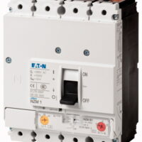
Circuit-breaker
Protective function
System and cable protection
Standard/Approval
IEC
Installation type
Fixed
Release system
Thermomagnetic release
Construction size
NZM2
Number of poles
3 pole
Standard equipment
Screw connection
Switching capacity
400/415 V 50 Hz [Icu ]
50 kA
Rated current = rated uninterrupted current [In = Iu ]
Rated current = rated uninterrupted current [In = Iu]
160 A
Setting range
Overload trip [Ir ]
[Ir ]
125 – 160 A
Short-circuit releases [Irm ]Non-delayed
 [Ii = In x …]
6 – 10
Short-circuit releases [Irm ]
960 – 1600 A
TECHNICAL DATA
General
Standards
IEC/EN 60947
Protection against direct contact
Finger and back of hand proof to VDE 0106 Part 100
Climatic proofing
Damp heat, constant, to IEC 60068-2-78
Damp heat, cyclic, to IEC 60068-2-30
Damp heat, cyclic, to IEC 60068-2-30
Ambient temperatureAmbient temperature, storage
– 40 – + 70 °C
Ambient temperatureOperation
-25 – +70 °C
Mechanical shock resistance (10 ms half-sinusoidal shock) according to IEC 60068-2-27
20 (half-sinusoidal shock 20 ms) g
Safe isolation to EN 61140Between auxiliary contacts and main contacts
500 V AC
Safe isolation to EN 61140between the auxiliary contacts
300 V AC
Mounting position
| Vertical and 90° in all directions | |
| |
With XFI earth-fault release: |
| – NZM1, N1, NZM2, N2: vertical and 90° in all directions | |
| with plug-in unit | |
| – NZM1, N1, NZM2, N2: vertical, 90° right/left | |
| with withdrawable unit: | |
| – NZM3, N3: vertical, 90° right/left | |
| – NZM4, N4: vertical | |
| with remote operator: | |
| – NZM2, N(S)2, NZM3, N(S)3, NZM4, N(S)4: vertical and 90° in all directions | |
Direction of incoming supply
as required
Degree of protectionDevice
In the operating controls area: IP20 (basic degree of protection)
Degree of protectionEnclosures
With insulating surround: IP40
With door coupling rotary handle: IP66
With door coupling rotary handle: IP66
Degree of protectionTerminations
Tunnel terminal: IP10
Phase isolator and strip terminal: IP00
Phase isolator and strip terminal: IP00
Other technical data (sheet catalogue)
Circuit-breakers
Rated current = rated uninterrupted current [In = Iu]
160 A
Rated surge voltage invariability [Uimp ]Main contacts
8000 V
Rated surge voltage invariability [Uimp ]Auxiliary contacts
6000 V
Rated operational voltage [Ue]
690 V AC
Rated operational voltage [Ue]
750 V DC
The following settings are required in order to ensure correct tripping:
The fast-response release will take longer to respond when used for DC applications. Because of this, the setting on the trip block inscription, which is specified for AC currents, must be set to a lower value for DC currents.
DC correction factor for instantaneous release response value:
o NZM1: 1.25
o NZM2: 1.35
o NZM3: 1.45
Example: NZM3 Ie = 500A. Desired DC tripping current: 10 * Ie = 5000A.
Calculation:
• Desired DC value / correction factor = AC setting on trip block
• 5000A / 1.45 = 3448 A ~ 7 * Ie = Value that needs to be set on the trip block
Permitted circuit configurations:
| |
|
Overvoltage category/pollution degree
III/3
Rated insulation voltage [Ui ]
1000 V
Use in unearthed supply systems
≦ 690 V
Switching capacity
Rated short-circuit making capacity [Icm ]240 V [Icm ]
187 kA
Rated short-circuit making capacity [Icm ]400/415 V [Icm ]
105 kA
Rated short-circuit making capacity [Icm ]440 V 50/60 Hz [Icm ]
74 kA
Rated short-circuit making capacity [Icm ]525 V 50/60 Hz [Icm ]
53 kA
Rated short-circuit making capacity [Icm ]690 V 50/60 H [Ic]
40 kA
Rated short-circuit breaking capacity Icn [Icn ]Icu to IEC/EN 60947 test cycle O-t-CO [Icu]240 V 50/60 Hz [Icu ]
85 kA
Rated short-circuit breaking capacity Icn [Icn ]Icu to IEC/EN 60947 test cycle O-t-CO [Icu]400/415 V 50/60 Hz [Icu ]
50 kA
Rated short-circuit breaking capacity Icn [Icn ]Icu to IEC/EN 60947 test cycle O-t-CO [Icu]440 V 50/60 Hz [Icu ]
35 kA
Rated short-circuit breaking capacity Icn [Icn ]Icu to IEC/EN 60947 test cycle O-t-CO [Icu]525 V 50/60 Hz [Icu ]
25 kA
Rated short-circuit breaking capacity Icn [Icn ]Icu to IEC/EN 60947 test cycle O-t-CO [Icu]690 V 50/60 Hz [Icu ]
20 kA
Rated short-circuit breaking capacity Icn [Icn ]Icu to IEC/EN 60947 test cycle O-t-CO [Icu]500 V DC [Icu]
30 kA
Rated short-circuit breaking capacity Icn [Icn ]Icu to IEC/EN 60947 test cycle O-t-CO [Icu]750 V DC [Icu]
30 kA
Rated short-circuit breaking capacity Icn [Icn ]Ics to IEC/EN 60947 test cycle O-t-CO-t-CO [Ics]240 V 50/60 Hz [Ics ]
85 kA
Rated short-circuit breaking capacity Icn [Icn ]Ics to IEC/EN 60947 test cycle O-t-CO-t-CO [Ics]400/415 V 50/60 Hz [Ics ]
50 kA
Rated short-circuit breaking capacity Icn [Icn ]Ics to IEC/EN 60947 test cycle O-t-CO-t-CO [Ics]440 V 50/60 Hz [Ics ]
35 kA
Rated short-circuit breaking capacity Icn [Icn ]Ics to IEC/EN 60947 test cycle O-t-CO-t-CO [Ics]525 V 50/60 Hz [Ics ]
25 kA
Rated short-circuit breaking capacity Icn [Icn ]Ics to IEC/EN 60947 test cycle O-t-CO-t-CO [Ics]690 V 50/60 Hz [Ics]
5 kA
Rated short-circuit breaking capacity Icn [Icn ]Ics to IEC/EN 60947 test cycle O-t-CO-t-CO [Ics]500 V DC [Ics]
7.5 kA
Rated short-circuit breaking capacity Icn [Icn ]Ics to IEC/EN 60947 test cycle O-t-CO-t-CO [Ics]750 V DC [Ics]
7.5 kA
Rated short-circuit breaking capacity Icn [Icn ]
Maximum back-up fuse, if the expected short-circuit currents at the installation location exceed the switching capacity of the circuit-breaker.
Rated short-time withstand currentt = 0.3 s [Icw ]
1.9 kA
Rated short-time withstand currentt = 1 s [Icw ]
1.9 kA
Utilization category to IEC/EN 60947-2
A
Lifespan, mechanical(of which max. 50 % trip by shunt/undervoltage release) [Operations]
20000
Lifespan, electricalAC-1400 V 50/60 Hz [Operations]
10000
Lifespan, electricalAC-1415 V 50/60 Hz [Operations]
10000
Lifespan, electricalAC-1690 V 50/60 Hz [Operations]
7500
Lifespan, electricalAC–3400 V 50/60 Hz [Operations]
6500
Lifespan, electricalAC–3415 V 50/60 Hz [Operations]
6500
Lifespan, electricalAC–3690 V 50/60 Hz [Operations]
5000
Lifespan, electricalDC-1500 V DC [Operations]
7500
Lifespan, electricalDC-1750 V DC [Operations]
7500
Lifespan, electricalDC – 3500 V DC [Operations]
3000
Lifespan, electricalDC – 3750 V DC [Operations]
3000
Lifespan, electricalMax. operating frequency
120 Ops/h
Total break time at short-circuit
< 10 ms
Terminal capacity
Standard equipment
Screw connection
Optional accessories
Box terminal
Tunnel terminal
connection on rear
Tunnel terminal
connection on rear
Round copper conductorBox terminalSolid
1 x (10 – 16)
2 x (6 – 16) mm2
2 x (6 – 16) mm2
Round copper conductorBox terminalStranded
1 x (25 – 185)
2 x (25 – 70) mm2
2 x (25 – 70) mm2
Round copper conductorTunnel terminalSolid
1 x 16 mm2
Round copper conductorTunnel terminalStranded1-hole
1 x (25 – 185) mm2
Round copper conductorBolt terminal and rear-side connectionDirect on the switchSolid
1 x (10 – 16)
2 x (6 – 16) mm2
2 x (6 – 16) mm2
Round copper conductorBolt terminal and rear-side connectionDirect on the switchStranded
1 x (25 – 185)
2 x (25 – 70) mm2
2 x (25 – 70) mm2
Al circular conductorTunnel terminalSolid
1 x 16 mm2
Al circular conductorTunnel terminalStrandedStranded
1 x (25 – 185) mm2
Al circular conductorBolt terminal and rear-side connectionDirect on the switchSolid
1 x (10 – 16)
2 x (10 – 16) mm2
2 x (10 – 16) mm2
Al circular conductorBolt terminal and rear-side connectionDirect on the switchStranded
1 x (25 – 50)
2 x (25 – 50) mm2
2 x (25 – 50) mm2
Cu strip (number of segments x width x segment thickness)Box terminal [min.]
2 x 9 x 0.8 mm
Cu strip (number of segments x width x segment thickness)Box terminal [max.]
10 x 16 x 0.8
(2x) 8 x 15.5 x 0,8 mm
(2x) 8 x 15.5 x 0,8 mm
Cu strip (number of segments x width x segment thickness)Bolt terminal and rear-side connectionFlat copper strip, with holes [min.]
2 x 16 x 0.8 mm
Cu strip (number of segments x width x segment thickness)Bolt terminal and rear-side connectionFlat copper strip, with holes [max.]
10 x 24 x 0.8 mm
Copper busbar (width x thickness) [mm]Bolt terminal and rear-side connectionScrew connection
M8
Copper busbar (width x thickness) [mm]Bolt terminal and rear-side connectionDirect on the switch [min.]
16 x 5 mm
Copper busbar (width x thickness) [mm]Bolt terminal and rear-side connectionDirect on the switch [max.]
24 x 8 mm
Control cables
1 x (0.75 – 2.5)
2 x (0.75 – 1.5) mm2
2 x (0.75 – 1.5) mm2
DESIGN VERIFICATION AS PER IEC/EN 61439
Technical data for design verification
Rated operational current for specified heat dissipation [In]
160 A
Equipment heat dissipation, current-dependent [Pvid]
38.4 W
Operating ambient temperature min.
-25 °C
Operating ambient temperature max.
+70 °C
IEC/EN 61439 design verification
10.2 Strength of materials and parts10.2.2 Corrosion resistance
Meets the product standard’s requirements.
10.2 Strength of materials and parts10.2.3.1 Verification of thermal stability of enclosures
Meets the product standard’s requirements.
10.2 Strength of materials and parts10.2.3.2 Verification of resistance of insulating materials to normal heat
Meets the product standard’s requirements.
10.2 Strength of materials and parts10.2.3.3 Verification of resistance of insulating materials to abnormal heat and fire due to internal electric effects
Meets the product standard’s requirements.
10.2 Strength of materials and parts10.2.4 Resistance to ultra-violet (UV) radiation
Meets the product standard’s requirements.
10.2 Strength of materials and parts10.2.5 Lifting
Does not apply, since the entire switchgear needs to be evaluated.
10.2 Strength of materials and parts10.2.6 Mechanical impact
Does not apply, since the entire switchgear needs to be evaluated.
10.2 Strength of materials and parts10.2.7 Inscriptions
Meets the product standard’s requirements.
10.3 Degree of protection of ASSEMBLIES
Does not apply, since the entire switchgear needs to be evaluated.
10.4 Clearances and creepage distances
Meets the product standard’s requirements.
10.5 Protection against electric shock
Does not apply, since the entire switchgear needs to be evaluated.
10.6 Incorporation of switching devices and components
Does not apply, since the entire switchgear needs to be evaluated.
10.7 Internal electrical circuits and connections
Is the panel builder’s responsibility.
10.8 Connections for external conductors
Is the panel builder’s responsibility.
10.9 Insulation properties10.9.2 Power-frequency electric strength
Is the panel builder’s responsibility.
10.9 Insulation properties10.9.3 Impulse withstand voltage
Is the panel builder’s responsibility.
10.9 Insulation properties10.9.4 Testing of enclosures made of insulating material
Is the panel builder’s responsibility.
10.10 Temperature rise
The panel builder is responsible for the temperature rise calculation. Eaton will provide heat dissipation data for the devices.
10.11 Short-circuit rating
Is the panel builder’s responsibility. The specifications for the switchgear must be observed.
10.12 Electromagnetic compatibility
Is the panel builder’s responsibility. The specifications for the switchgear must be observed.
10.13 Mechanical function
The device meets the requirements, provided the information in the instruction leaflet (IL) is observed.
TECHNICAL DATA ETIM 8.0
Low-voltage industrial components (EG000017) / Power circuit-breaker for trafo/generator/installation protection (EC000228)
Electric engineering, automation, process control engineering / Low-voltage switch technology / Circuit breaker (LV < 1 kV) / Circuit breaker for power transformer, generator and system protection ([email protected] [AJZ716013])
Rated permanent current Iu
160 A
Rated voltage
690 – 690 V
Rated short-circuit breaking capacity lcu at 400 V, 50 Hz
50 kA
Overload release current setting
125 – 160 A
Adjustment range short-term delayed short-circuit release
0 – 0 A
Adjustment range undelayed short-circuit release
960 – 1600 A
Integrated earth fault protection
No
Type of electrical connection of main circuit
Screw connection
Device construction
Built-in device fixed built-in technique
Suitable for DIN rail (top hat rail) mounting
No
DIN rail (top hat rail) mounting optional
Yes
Number of auxiliary contacts as normally closed contact
0
Number of auxiliary contacts as normally open contact
0
Number of auxiliary contacts as change-over contact
0
With switched-off indicator
No
With integrated under voltage release
No
Number of poles
3
Position of connection for main current circuit
Front side
Type of control element
Rocker lever
Complete device with protection unit
Yes
Motor drive integrated
No
Motor drive optional
Yes
Degree of protection (IP)
IP20
CHARACTERISTICS
Characteristic curve
Characteristic curve
Let-through current
Characteristic curve
Let-through energy
DIMENSIONS
① Blow out area, minimum clearance to adjacent parts
② Minimum clearance to adjacent parts
② Minimum clearance to adjacent parts