DELIVERY PROGRAM
Product range
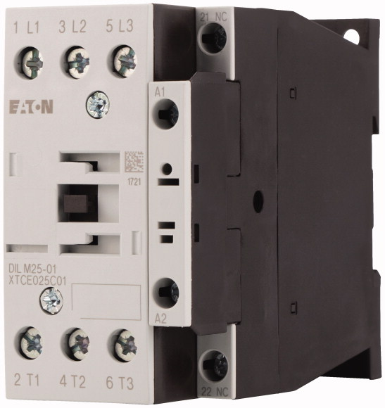
Contactors
Application
Contactors for Motors
Subrange
Contactors up to 170 A, 3 pole
Utilization category
AC-1: Non-inductive or slightly inductive loads, resistance furnaces
AC-3/AC-3e: Normal AC induction motors: Starting, switching off while running
AC-4: Normal AC induction motors: starting, plugging, reversing, inching
AC-3/AC-3e: Normal AC induction motors: Starting, switching off while running
AC-4: Normal AC induction motors: starting, plugging, reversing, inching
Notes
Also suitable for motors with efficiency class IE3.
Connection technique
Screw terminals
Number of poles
3 pole
Rated operational current
AC-3Notes
At maximum permissible ambient temperature (open.)
Also tested according to AC-3e.
Also tested according to AC-3e.
AC-3380 V 400 V [Ie]
25 A
AC-1Conventional free air thermal current, 3 pole, 50 – 60 HzOpenat 40 °C [Ith =Ie]
45 A
AC-1Conventional free air thermal current, 3 pole, 50 – 60 Hzenclosed [Ith ]
36 A
AC-1Conventional free air thermal current, 1 poleopen [Ith ]
100 A
AC-1Conventional free air thermal current, 1 poleenclosed [Ith ]
90 A
Max. rating for three-phase motors, 50 – 60 Hz
AC-3220 V 230 V [P]
7.5 kW
AC-3380 V 400 V [P]
11 kW
AC-3660 V 690 V [P]
14 kW
AC-4220 V 230 V [P]
3.5 kW
AC-4380 V 400 V [P]
6 kW
AC-4660 V 690 V [P]
8.5 kW
Contacts
N/C = Normally closed
1 NC
Can be combined with auxiliary contact
DILA-XHI(V)…
DILM32-XHI11-S
DILM32-XHI11-S
Actuating voltage
230 V 50 Hz, 240 V 60 Hz
Voltage AC/DC
AC operation
Connection to SmartWire-DT
no
Instructions
Contacts to EN 50 012.
with mirror contact.
with mirror contact.
Frame size
2
TECHNICAL DATA
General
Standards
IEC/EN 60947, VDE 0660, UL, CSA
Lifespan, mechanicalAC operated [Operations]
10 x 106
Operating frequency, mechanicalAC operated [Operations/h]
5000
Climatic proofing
Damp heat, constant, to IEC 60068-2-78
Damp heat, cyclic, to IEC 60068-2-30
Damp heat, cyclic, to IEC 60068-2-30
Ambient temperatureOpen
-25 – +60 °C
Ambient temperatureEnclosed
– 25 – 40 °C
Ambient temperatureStorage
– 40 – 80 °C
Mechanical shock resistance (IEC/EN 60068-2-27)Half-sinusoidal shock, 10 msMain contactsN/O contact
10 g
Mechanical shock resistance (IEC/EN 60068-2-27)Half-sinusoidal shock, 10 msAuxiliary contactsN/O contact
7 g
Mechanical shock resistance (IEC/EN 60068-2-27)Half-sinusoidal shock, 10 msAuxiliary contactsN/C contact
5 g
Mechanical shock resistance (IEC/EN 60068-2-27) when tabletop-mountedHalf-sinusoidal shock, 10 msMain contactsN/O contact
6.9 g
Mechanical shock resistance (IEC/EN 60068-2-27) when tabletop-mountedHalf-sinusoidal shock, 10 msAuxiliary contactsN/O contact
5.3 g
Mechanical shock resistance (IEC/EN 60068-2-27) when tabletop-mountedHalf-sinusoidal shock, 10 msAuxiliary contactsN/C contact
3.5 g
Degree of Protection
IP00
Protection against direct contact when actuated from front (EN 50274)
Finger and back-of-hand proof
Altitude
Max. 2000 m
WeightAC operated
0.428 kg
Screw connector terminalsTerminal capacity main cableSolid
1 x (0.75 – 16)
2 x (0.75 – 10) mm2
2 x (0.75 – 10) mm2
Screw connector terminalsTerminal capacity main cableFlexible with ferrule
1 x (0.75 – 16)
2 x (0.75 – 10) mm2
2 x (0.75 – 10) mm2
Screw connector terminalsTerminal capacity main cableStranded
1 x 16 mm2
Screw connector terminalsTerminal capacity main cableSolid or stranded
single 18 – 6, double 18 – 8 AWG
Screw connector terminalsTerminal capacity main cableStripping length
10 mm
Screw connector terminalsTerminal capacity main cableTerminal screw
M5
Screw connector terminalsTerminal capacity main cableTightening torque
3.2 Nm
Screw connector terminalsTerminal capacity main cableToolPozidriv screwdriver
2 Size
Screw connector terminalsTerminal capacity main cableToolStandard screwdriver
0.8 x 5.5
1 x 6 mm
1 x 6 mm
Screw connector terminalsTerminal capacity control circuit cablesSolid
1 x (0.75 – 4)
2 x (0.75 – 2.5) mm2
2 x (0.75 – 2.5) mm2
Screw connector terminalsTerminal capacity control circuit cablesFlexible with ferrule
1 x (0.75 – 2.5)
2 x (0.75 – 2.5) mm2
2 x (0.75 – 2.5) mm2
Screw connector terminalsTerminal capacity control circuit cablesSolid or stranded
18 – 14 AWG
Screw connector terminalsTerminal capacity control circuit cablesStripping length
10 mm
Screw connector terminalsTerminal capacity control circuit cablesTerminal screw
M3.5
Screw connector terminalsTerminal capacity control circuit cablesTightening torque
1.2 Nm
Screw connector terminalsTerminal capacity control circuit cablesToolPozidriv screwdriver
2 Size
Screw connector terminalsTerminal capacity control circuit cablesToolStandard screwdriver
0.8 x 5.5
1 x 6 mm
1 x 6 mm
Main conducting paths
Rated impulse withstand voltage [Uimp]
8000 V AC
Overvoltage category/pollution degree
III/3
Rated insulation voltage [Ui]
690 V AC
Rated operational voltage [Ue]
690 V AC
Safe isolation to EN 61140between coil and contacts
440 V AC
Safe isolation to EN 61140between the contacts
440 V AC
Making capacity (p.f. to IEC/EN 60947) [Up to 690 V]
350 A
Breaking capacity220 V 230 V
250 A
Breaking capacity380 V 400 V
250 A
Breaking capacity500 V
250 A
Breaking capacity660 V 690 V
150 A
Short-circuit ratingShort-circuit protection maximum fuseType “2” coordination400 V [gG/gL 500 V]
35 A
Short-circuit ratingShort-circuit protection maximum fuseType “2” coordination690 V [gG/gL 690 V]
35 A
Short-circuit ratingShort-circuit protection maximum fuseType “1” coordination400 V [gG/gL 500 V]
100 A
Short-circuit ratingShort-circuit protection maximum fuseType “1” coordination690 V [gG/gL 690 V]
50 A
AC
AC-1Rated operational currentConventional free air thermal current, 3 pole, 50 – 60 HzOpenat 40 °C [Ith =Ie]
45 A
AC-1Rated operational currentConventional free air thermal current, 3 pole, 50 – 60 HzOpenat 50 °C [Ith =Ie]
43 A
AC-1Rated operational currentConventional free air thermal current, 3 pole, 50 – 60 HzOpenat 55 °C [Ith =Ie]
42 A
AC-1Rated operational currentConventional free air thermal current, 3 pole, 50 – 60 HzOpenat 60 °C [Ith =Ie]
40 A
AC-1Rated operational currentConventional free air thermal current, 3 pole, 50 – 60 Hzenclosed [Ith ]
36 A
AC-1Rated operational currentConventional free air thermal current, 1 poleopen [Ith ]
100 A
AC-1Rated operational currentConventional free air thermal current, 1 poleenclosed [Ith ]
90 A
AC-3Rated operational currentOpen, 3-pole: 50 – 60 HzNotes
At maximum permissible ambient temperature (open.)
Also tested according to AC-3e.
Also tested according to AC-3e.
AC-3Rated operational currentOpen, 3-pole: 50 – 60 Hz220 V 230 V [Ie]
25 A
AC-3Rated operational currentOpen, 3-pole: 50 – 60 Hz240 V [Ie]
25 A
AC-3Rated operational currentOpen, 3-pole: 50 – 60 Hz380 V 400 V [Ie]
25 A
AC-3Rated operational currentOpen, 3-pole: 50 – 60 Hz415 V [Ie]
25 A
AC-3Rated operational currentOpen, 3-pole: 50 – 60 Hz440V [Ie]
25 A
AC-3Rated operational currentOpen, 3-pole: 50 – 60 Hz500 V [Ie]
25 A
AC-3Rated operational currentOpen, 3-pole: 50 – 60 Hz660 V 690 V [Ie]
15 A
AC-3Motor rating [P]220 V 230 V [P]
7.5 kW
AC-3Motor rating [P]240V [P]
8.5 kW
AC-3Motor rating [P]380 V 400 V [P]
11 kW
AC-3Motor rating [P]415 V [P]
14.5 kW
AC-3Motor rating [P]440 V [P]
15.5 kW
AC-3Motor rating [P]500 V [P]
17.5 kW
AC-3Motor rating [P]660 V 690 V [P]
14 kW
AC-4Open, 3-pole: 50 – 60 Hz220 V 230 V [Ie ]
13 A
AC-4Open, 3-pole: 50 – 60 Hz240 V [Ie ]
13 A
AC-4Open, 3-pole: 50 – 60 Hz380 V 400 V [Ie ]
13 A
AC-4Open, 3-pole: 50 – 60 Hz415 V [Ie ]
13 A
AC-4Open, 3-pole: 50 – 60 Hz440 V [Ie ]
13 A
AC-4Open, 3-pole: 50 – 60 Hz500 V [Ie ]
13 A
AC-4Open, 3-pole: 50 – 60 Hz660 V 690 V [Ie ]
10 A
AC-4Motor rating [P]220 V 230 V [P]
3.5 kW
AC-4Motor rating [P]240 V [P]
4 kW
AC-4Motor rating [P]380 V 400 V [P]
6 kW
AC-4Motor rating [P]415 V [P]
6.5 kW
AC-4Motor rating [P]440 V [P]
7 kW
AC-4Motor rating [P]500 V [P]
8 kW
AC-4Motor rating [P]660 V 690 V [P]
8.5 kW
DC
Rated operational current, openDC-160 V [Ie ]
40 A
Rated operational current, openDC-1110 V [Ie ]
40 A
Rated operational current, openDC-1220 V [Ie ]
40 A
Current heat loss
3 pole, at Ith (60°)
10.8 W
Current heat loss at Ie to AC-3/400 V
4.2 W
Impedance per pole
2.7 mΩ
Magnet systems
Voltage toleranceAC operated [Pick-up]
0.8 – 1.1 x Uc
Voltage toleranceDrop-out voltage AC operated [Drop-out]
0.3 – 0.6 x Uc
Power consumption of the coil in a cold state and 1.0 x US50 Hz [Pick-up]
52 VA
Power consumption of the coil in a cold state and 1.0 x US50 Hz [Sealing]
7.1 VA
Power consumption of the coil in a cold state and 1.0 x US50 Hz [Sealing]
2.1 W
Power consumption of the coil in a cold state and 1.0 x US60 Hz [Pick-up]
67 VA
Power consumption of the coil in a cold state and 1.0 x US60 Hz [Sealing]
8.7 VA
Power consumption of the coil in a cold state and 1.0 x US60 Hz [Sealing]
2.1 W
Duty factor
100 % DF
Changeover time at 100 % US (recommended value)Main contactsAC operatedClosing delay
16 – 22 ms
Changeover time at 100 % US (recommended value)Main contactsAC operatedOpening delay
8 – 14 ms
Changeover time at 100 % US (recommended value)Arcing time
10 ms
Electromagnetic compatibility (EMC)
Emitted interference
to EN 60947-1
Interference immunity
to EN 60947-1
Rating data for approved types
Switching capacityMaximum motor ratingThree-phase200 V
208 V
208 V
7.5 HP
Switching capacityMaximum motor ratingThree-phase230 V
240 V
240 V
10 HP
Switching capacityMaximum motor ratingThree-phase460 V
480 V
480 V
15 HP
Switching capacityMaximum motor ratingThree-phase575 V
600 V
600 V
20 HP
Switching capacityMaximum motor ratingSingle-phase115 V
120 V
120 V
2 HP
Switching capacityMaximum motor ratingSingle-phase230 V
240 V
240 V
5 HP
Switching capacityGeneral use
40 A
Auxiliary contactsPilot DutyAC operated
A600
Auxiliary contactsPilot DutyDC operated
P300
Auxiliary contactsGeneral UseAC
600 V
Auxiliary contactsGeneral UseAC
10 A
Auxiliary contactsGeneral UseDC
250 V
Auxiliary contactsGeneral UseDC
1 A
Short Circuit Current RatingBasic RatingSCCR
5 kA
Short Circuit Current RatingBasic Ratingmax. Fuse
125 A
Short Circuit Current RatingBasic Ratingmax. CB
125 A
Short Circuit Current Rating480 V High FaultSCCR (fuse)
10/100 kA
Short Circuit Current Rating480 V High Faultmax. Fuse
125/70 Class J A
Short Circuit Current Rating480 V High FaultSCCR (CB)
10/65 kA
Short Circuit Current Rating480 V High Faultmax. CB
50/32 A
Short Circuit Current Rating600 V High FaultSCCR (fuse)
10/100 kA
Short Circuit Current Rating600 V High Faultmax. Fuse
125/100 Class J A
Short Circuit Current Rating600 V High FaultSCCR (CB)
10/22 kA
Short Circuit Current Rating600 V High Faultmax. CB
50/32 A
Special Purpose RatingsElectrical Discharge Lamps (Ballast)480V 60Hz 3phase, 277V 60Hz 1phase
40 A
Special Purpose RatingsElectrical Discharge Lamps (Ballast)600V 60Hz 3phase, 347V 60Hz 1phase
40 A
Special Purpose RatingsIncandescent Lamps (Tungsten)480V 60Hz 3phase, 277V 60Hz 1phase
40 A
Special Purpose RatingsIncandescent Lamps (Tungsten)600V 60Hz 3phase, 347V 60Hz 1phase
40 A
Special Purpose RatingsResistance Air Heating480V 60Hz 3phase, 277V 60Hz 1phase
40 A
Special Purpose RatingsResistance Air Heating600V 60Hz 3phase, 347V 60Hz 1phase
40 A
Special Purpose RatingsRefrigeration Control (CSA only)LRA 480V 60Hz 3phase
240 A
Special Purpose RatingsRefrigeration Control (CSA only)FLA 480V 60Hz 3phase
40 A
Special Purpose RatingsRefrigeration Control (CSA only)LRA 600V 60Hz 3phase
180 A
Special Purpose RatingsRefrigeration Control (CSA only)FLA 600V 60Hz 3phase
30 A
Special Purpose RatingsDefinite Purpose Ratings (100,000 cycles acc. to UL 1995)LRA 480V 60Hz 3phase
150 A
Special Purpose RatingsDefinite Purpose Ratings (100,000 cycles acc. to UL 1995)FLA 480V 60Hz 3phase
25 A
Special Purpose RatingsElevator Control200V 60Hz 3phase
3 HP
Special Purpose RatingsElevator Control200V 60Hz 3phase
11 A
Special Purpose RatingsElevator Control240V 60Hz 3phase
5 HP
Special Purpose RatingsElevator Control240V 60Hz 3phase
15.2 A
Special Purpose RatingsElevator Control480V 60Hz 3phase
10 HP
Special Purpose RatingsElevator Control480V 60Hz 3phase
14 A
Special Purpose RatingsElevator Control600V 60Hz 3phase
15 HP
Special Purpose RatingsElevator Control600V 60Hz 3phase
17 A
DESIGN VERIFICATION AS PER IEC/EN 61439
Technical data for design verification
Rated operational current for specified heat dissipation [In]
25 A
Heat dissipation per pole, current-dependent [Pvid]
1.4 W
Equipment heat dissipation, current-dependent [Pvid]
4.2 W
Static heat dissipation, non-current-dependent [Pvs]
2.1 W
Heat dissipation capacity [Pdiss]
0 W
Operating ambient temperature min.
-25 °C
Operating ambient temperature max.
+60 °C
IEC/EN 61439 design verification
10.2 Strength of materials and parts10.2.2 Corrosion resistance
Meets the product standard’s requirements.
10.2 Strength of materials and parts10.2.3.1 Verification of thermal stability of enclosures
Meets the product standard’s requirements.
10.2 Strength of materials and parts10.2.3.2 Verification of resistance of insulating materials to normal heat
Meets the product standard’s requirements.
10.2 Strength of materials and parts10.2.3.3 Verification of resistance of insulating materials to abnormal heat and fire due to internal electric effects
Meets the product standard’s requirements.
10.2 Strength of materials and parts10.2.4 Resistance to ultra-violet (UV) radiation
Meets the product standard’s requirements.
10.2 Strength of materials and parts10.2.5 Lifting
Does not apply, since the entire switchgear needs to be evaluated.
10.2 Strength of materials and parts10.2.6 Mechanical impact
Does not apply, since the entire switchgear needs to be evaluated.
10.2 Strength of materials and parts10.2.7 Inscriptions
Meets the product standard’s requirements.
10.3 Degree of protection of ASSEMBLIES
Does not apply, since the entire switchgear needs to be evaluated.
10.4 Clearances and creepage distances
Meets the product standard’s requirements.
10.5 Protection against electric shock
Does not apply, since the entire switchgear needs to be evaluated.
10.6 Incorporation of switching devices and components
Does not apply, since the entire switchgear needs to be evaluated.
10.7 Internal electrical circuits and connections
Is the panel builder’s responsibility.
10.8 Connections for external conductors
Is the panel builder’s responsibility.
10.9 Insulation properties10.9.2 Power-frequency electric strength
Is the panel builder’s responsibility.
10.9 Insulation properties10.9.3 Impulse withstand voltage
Is the panel builder’s responsibility.
10.9 Insulation properties10.9.4 Testing of enclosures made of insulating material
Is the panel builder’s responsibility.
10.10 Temperature rise
The panel builder is responsible for the temperature rise calculation. Eaton will provide heat dissipation data for the devices.
10.11 Short-circuit rating
Is the panel builder’s responsibility. The specifications for the switchgear must be observed.
10.12 Electromagnetic compatibility
Is the panel builder’s responsibility. The specifications for the switchgear must be observed.
10.13 Mechanical function
The device meets the requirements, provided the information in the instruction leaflet (IL) is observed.
TECHNICAL DATA ETIM 8.0
Low-voltage industrial components (EG000017) / Power contactor, AC switching (EC000066)
Electric engineering, automation, process control engineering / Low-voltage switch technology / Contactor (LV) / Power contactor, AC switching ([email protected] [AAB718015])
Rated control supply voltage Us at AC 50HZ
230 – 230 V
Rated control supply voltage Us at AC 60HZ
240 – 240 V
Rated control supply voltage Us at DC
0 – 0 V
Voltage type for actuating
AC
Rated operation current Ie at AC-1, 400 V
45 A
Rated operation current Ie at AC-3, 400 V
25 A
Rated operation power at AC-3, 400 V
11 kW
Rated operation current Ie at AC-4, 400 V
13 A
Rated operation power at AC-4, 400 V
6 kW
Rated operation power NEMA
11 kW
Modular version
No
Number of auxiliary contacts as normally open contact
0
Number of auxiliary contacts as normally closed contact
1
Type of electrical connection of main circuit
Screw connection
Number of normally closed contacts as main contact
0
Number of normally open contacts as main contact
3
APPROVALS
Product Standards
IEC/EN 60947-4-1; UL 60947-4-1; CSA – C22.2 No. 60947-4-1-14; CE marking
UL File No.
E29096
UL Category Control No.
NLDX
CSA File No.
012528
CSA Class No.
2411-03, 3211-04
North America Certification
UL listed, CSA certified
Specially designed for North America
No
CHARACTERISTICS
Accessories
1: Overload relay
2: Suppressor
3: Auxiliary contact modules
2: Suppressor
3: Auxiliary contact modules
Squirrel-cage motor
Operating characteristics
Starting:from rest
Stopping:after attaining full running speed
Electrical characteristics
Make: up to 6 x rated motor current
Break: up to 1 x rated motor current
Utilization category
100 % AC-3
Typical applications
Compressors
Lifts
Mixers
Pumps
Escalators
Agitators
Fans
Conveyor belts
Centrifuges
Hinged flaps
Bucket-elevators
Air conditioning system
General drives in manufacturing and processing machines
Extreme switching duty
Squirrel-cage motor
Operating characteristics
Inching, plugging, reversing
Electrical characteristics
Make: up to 6 x rated motor current
Break: up to 6 x rated motor current
Utilization category
100 % AC-4
Typical applications
Printing presses
Wire-drawing machines
Centrifuges
Special drives for manufacturing and processing machines
Switching conditions for non-motor consumers, 3 pole, 4 pole
Operating characteristics
Non inductive and slightly inductive loads
Electrical characteristics
Switch on: 1 x rated operational current
Switch off: 1 x rated operational current
Utilization category
100 % AC-1
Typical examples of application
Electric heat
Operating characteristics
Non inductive and slightly inductive loads
Electrical characteristics
Switch on: 1 x rated operational current
Switch off: 1 x rated operational current
Utilization category
100 % AC-1
Typical examples of application
Electric heat

