DELIVERY PROGRAM
Accessories
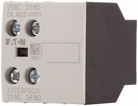
Auxiliary contact modules
Description
with interlocked opposing contacts
Function
for standard applications
Number of poles
2 pole
Connection technique
Screw terminals
Rated operational current
Conventional free air thermal current, 1 poleOpenat 60 °C [Ith]
16 A
AC-15220 V 230 V 240 V [Ie]
4 A
AC-15380 V 400 V 415 V [Ie]
4 A
Contacts
N/O = Normally open
1 N/O
N/C = Normally closed
1 NC
Mounting type
Front fixing
Contact sequence
For use with
DILM(C)7-10…
DILM(C)9-10…
DILM(C)12-10…
DILM(C)15-10…
DILM(C)17-10…
DILM(C)25-10…
DILM(C)32-10…
DILM38-10…
DILMP20…
DILMP32-10…
DILMP45-10…
DILL…
DILMF8-10…
DILMF11-10…
DILMF14-10…
DILMF17-10…
DILMF25-10…
DILMF32-10…
DILM(C)9-10…
DILM(C)12-10…
DILM(C)15-10…
DILM(C)17-10…
DILM(C)25-10…
DILM(C)32-10…
DILM38-10…
DILMP20…
DILMP32-10…
DILMP45-10…
DILL…
DILMF8-10…
DILMF11-10…
DILMF14-10…
DILMF17-10…
DILMF25-10…
DILMF32-10…
Type
Front mounting auxiliary contact
Instructions
Interlocked opposing contacts according to IEC/EN 60947-5-1 appendix L, inside the auxiliary contact modules, also for the integrated auxiliary contacts of the DILM 7 – DILM32
Auxiliary contacts used as mirror contacts according to IEC/EN 60947-4-1 Appendix F (not N/C late open)
Auxiliary contacts used as mirror contacts according to IEC/EN 60947-4-1 Appendix F (not N/C late open)
TECHNICAL DATA
General
Standards
IEC/EN 60947, VDE 0660, UL, CSA
Component lifespanat Ue = 230 V, AC-15, 3 A [Operations]
1.3 x 10⁶
Climatic proofing
Damp heat, constant, to IEC 60068-2-78
Damp heat, cyclic, to IEC 60068-2-30
Damp heat, cyclic, to IEC 60068-2-30
Ambient temperatureOpen
-25 – +60 °C
Ambient temperatureEnclosed
– 25 – 40 °C
Ambient temperatureAmbient temperature, storage
– 40 – 80 °C
Mechanical shock resistance (IEC/EN 60068-2-27)Half-sinusoidal shock, 10 msBasic unit with auxiliary contact moduleN/O contact
7 g
Mechanical shock resistance (IEC/EN 60068-2-27)Half-sinusoidal shock, 10 msBasic unit with auxiliary contact moduleN/C contact
5 g
Degree of Protection
IP20
Protection against direct contact when actuated from front (EN 50274)
Finger and back-of-hand proof
Weight
0.038 kg
Terminal capacitiesScrew terminalsSolid
1 x (0.75 – 2.5)
2 x (0.75 – 2.5) mm2
2 x (0.75 – 2.5) mm2
Terminal capacitiesScrew terminalsFlexible with ferrule
1 x (0.75 – 2.5)
2 x (0.75 – 2.5) mm2
2 x (0.75 – 2.5) mm2
Terminal capacitiesScrew terminalsSolid or stranded
18 – 14 AWG
Terminal capacitiesScrew terminalsPozidriv screwdriver
2 Size
Terminal capacitiesScrew terminalsStandard screwdriver
0.8 x 5.5
1 x 6 mm
1 x 6 mm
Terminal capacitiesScrew terminalsMax. tightening torque
1.2 Nm
Contacts
Interlocked opposing contacts within an auxiliary contact module (to IEC 60947-5-1 Annex L)
Yes
N/C contact (not late-break contact) suitable as a mirror contact (to IEC/EN 60947-4-1 Annex F)
DILM7 – DILM38
Rated impulse withstand voltage [Uimp]
6000 V AC
Overvoltage category/pollution degree
III/3
Rated insulation voltage [Ui]
690 V AC
Rated operational voltage [Ue]
500 V AC
Safe isolation to EN 61140between coil and auxiliary contacts
400 V AC
Safe isolation to EN 61140between the auxiliary contacts
400 V AC
Rated operational currentConventional free air thermal current, 1 poleat 60 °C [Ith]
16 A
Rated operational currentAC-15220 V 230 V 240 V [Ie]
4 A
Rated operational currentAC-15380 V 400 V 415 V [Ie]
4 A
Rated operational currentAC-15500 V [Ie]
1.5 A
Rated operational currentDC current
Switch-on and switch-off conditions based on DC-13, time constant as specified.
Rated operational currentDC currentDC L/R ≦ 15 msContacts in series:1 [24 V]
10 A
Rated operational currentDC currentDC L/R ≦ 15 msContacts in series:1 [60 V]
6 A
Rated operational currentDC currentDC L/R ≦ 15 msContacts in series:1 [110 V]
3 A
Rated operational currentDC currentDC L/R ≦ 15 msContacts in series:1 [220 V]
1 A
Rated operational currentDC currentDC-13 (6xP)24 V [Ie ]
2.5 A
Rated operational currentDC currentDC-13 (6xP)60 V [Ie ]
1 A
Rated operational currentDC currentDC-13 (6xP)110 V [Ie ]
0.5 A
Rated operational currentDC currentDC-13 (6xP)220 V [Ie ]
0.25 A
Rated operational currentControl circuit reliability [Failure rate]
<10-8, < one failure at 100 million operations
(at Ue = 24 V DC, Umin = 17 V, Imin = 5.4 mA) λ
(at Ue = 24 V DC, Umin = 17 V, Imin = 5.4 mA) λ
Short-circuit rating without weldingShort-circuit protection maximum fuse500 V
10 A gG/gL
Current heat loss at IthAC operated
2.6 W
Current heat loss at IthDC operated
2.6 W
Current heat loss at IthCurrent heat loss per auxiliary circuit at Ie (AC-15/230 V)
0.16 CO
Rating data for approved types
Auxiliary contactsPilot DutyAC operated
A600
Auxiliary contactsPilot DutyDC operated
P300
Auxiliary contactsGeneral UseAC
600 V
Auxiliary contactsGeneral UseAC
10 A
Auxiliary contactsGeneral UseDC
250 V
Auxiliary contactsGeneral UseDC
1 A
DESIGN VERIFICATION AS PER IEC/EN 61439
Technical data for design verification
Rated operational current for specified heat dissipation [In]
4 A
Heat dissipation per pole, current-dependent [Pvid]
0.16 W
Equipment heat dissipation, current-dependent [Pvid]
0 W
Static heat dissipation, non-current-dependent [Pvs]
0 W
Heat dissipation capacity [Pdiss]
0 W
Operating ambient temperature min.
-25 °C
Operating ambient temperature max.
+60 °C
IEC/EN 61439 design verification
10.2 Strength of materials and parts10.2.2 Corrosion resistance
Meets the product standard’s requirements.
10.2 Strength of materials and parts10.2.3.1 Verification of thermal stability of enclosures
Meets the product standard’s requirements.
10.2 Strength of materials and parts10.2.3.2 Verification of resistance of insulating materials to normal heat
Meets the product standard’s requirements.
10.2 Strength of materials and parts10.2.3.3 Verification of resistance of insulating materials to abnormal heat and fire due to internal electric effects
Meets the product standard’s requirements.
10.2 Strength of materials and parts10.2.4 Resistance to ultra-violet (UV) radiation
Meets the product standard’s requirements.
10.2 Strength of materials and parts10.2.5 Lifting
Does not apply, since the entire switchgear needs to be evaluated.
10.2 Strength of materials and parts10.2.6 Mechanical impact
Does not apply, since the entire switchgear needs to be evaluated.
10.2 Strength of materials and parts10.2.7 Inscriptions
Meets the product standard’s requirements.
10.3 Degree of protection of ASSEMBLIES
Does not apply, since the entire switchgear needs to be evaluated.
10.4 Clearances and creepage distances
Meets the product standard’s requirements.
10.5 Protection against electric shock
Does not apply, since the entire switchgear needs to be evaluated.
10.6 Incorporation of switching devices and components
Does not apply, since the entire switchgear needs to be evaluated.
10.7 Internal electrical circuits and connections
Is the panel builder’s responsibility.
10.8 Connections for external conductors
Is the panel builder’s responsibility.
10.9 Insulation properties10.9.2 Power-frequency electric strength
Is the panel builder’s responsibility.
10.9 Insulation properties10.9.3 Impulse withstand voltage
Is the panel builder’s responsibility.
10.9 Insulation properties10.9.4 Testing of enclosures made of insulating material
Is the panel builder’s responsibility.
10.10 Temperature rise
The panel builder is responsible for the temperature rise calculation. Eaton will provide heat dissipation data for the devices.
10.11 Short-circuit rating
Is the panel builder’s responsibility. The specifications for the switchgear must be observed.
10.12 Electromagnetic compatibility
Is the panel builder’s responsibility. The specifications for the switchgear must be observed.
10.13 Mechanical function
The device meets the requirements, provided the information in the instruction leaflet (IL) is observed.
TECHNICAL DATA ETIM 8.0
Low-voltage industrial components (EG000017) / Auxiliary contact block (EC000041)
Electric engineering, automation, process control engineering / Low-voltage switch technology / Component for low-voltage switching technology / Auxiliary switch block ([email protected] [AKN342013])
Number of contacts as change-over contact
0
Number of contacts as normally open contact
1
Number of contacts as normally closed contact
1
Number of fault-signal switches
0
Rated operation current Ie at AC-15, 230 V
6 A
Type of electric connection
Screw connection
Model
Top mounting
Mounting method
Front fastening
Lamp holder
None
APPROVALS
Product Standards
IEC/EN 60947-4-1; UL 508; CSA-C22.2 No. 14-05; CE marking
UL File No.
E29184
UL Category Control No.
NKCR
CSA File No.
012528
CSA Class No.
3211-03
North America Certification
UL listed, CSA certified
Specially designed for North America
No
DIMENSIONS
Contactor with auxiliary contact module